


Rotary air valves are widely used to control the discharge of powders, granules and pellets from hoppers, silos, cyclones, dust collectors and pneumatic conveying systems. Although they are sometimes treated as simple mechanical feeders, the correct valve selection has a major influence on material flow, air leakage, throughput, product damage, wear and maintenance requirements.
APS Technology Australia’s rotary air valve range includes configurations for general powders and granules, pneumatic conveying, dust collection, sanitary processing, abrasive materials and products that are vulnerable to shearing or breakage. The objective is not simply to match a valve to a flange size, but to select a design that suits the material and the operating conditions of the complete process.
What Does a Rotary Air Valve Do?
A rotary air valve, also called a rotary airlock or rotary feeder, contains a rotating pocketed rotor within a close-fitting housing. Material enters through the inlet, fills the rotor pockets and is discharged as the rotor turns.
Depending on the application, the valve may perform several functions:
- Control the discharge of bulk material from a hopper or silo
- Meter material into downstream equipment
- Maintain separation between areas operating at different pressures
- Feed material into a pneumatic conveying line
- Discharge dust from a cyclone or baghouse
- Reduce uncontrolled air movement through the material outlet
The rotor, housing, end plates, bearings, seals and drive arrangement must work together under the actual material, pressure and temperature conditions.
Why Rotary Valve Selection Matters
Two rotary valves with the same nominal inlet size may perform very differently.
A valve selected for free-flowing plastic granules may not be suitable for abrasive cement powder, sticky food ingredients or fragile pellets. Incorrect selection can result in:
- Material leakage
- Excessive air bypass
- Rotor jamming
- Product shearing
- Reduced throughput
- Premature housing or rotor wear
- Motor overload
- Poor feeding accuracy
- Frequent cleaning and maintenance
The valve must therefore be selected around the process rather than selected only from a dimensional drawing.
Discharging and Metering Powders and Granules
General-purpose rotary valves can be installed below:
- Storage silos
- Day bins
- Hoppers
- Weighing systems
- Mixers
- Cyclones
- Filters
- Process equipment
These valves can provide controlled discharge or approximate volumetric feeding of powders and granules.
The catalogue range includes standard discharge and metering valves manufactured in cast iron or stainless steel, with special-material options including nickel alloys, titanium and other corrosion-resistant materials. Suitable configurations are available for vacuum and pressure applications, with selected models designed for pressure differentials up to 1.5 barg and elevated temperatures up to approximately 300°C.
For demanding applications, rotor construction, internal clearances, shaft seals and material-contact surfaces should be selected according to the product being handled.
Rotary Valves for Pneumatic Conveying
In pneumatic conveying systems, the rotary valve must transfer material into an air stream while limiting pressure loss and leakage.
A blow-through rotary valve can be connected directly to a conveying pipeline. Instead of dropping the material into a separate conveying tee, the conveying air passes through the lower section of the valve and carries the material away.
These valves are commonly considered for:
- Food powders
- Grain products
- Chemical powders
- Plastic materials
- Pharmaceutical ingredients
- Fine industrial powders
The valve must be evaluated against conveying pressure, material density, rotor speed, air leakage and the required feed rate. The catalogue includes blow-through configurations designed for pneumatic conveying duties up to 1.5 barg.
Dust Collector and Cyclone Discharge
Dust collectors and cyclones require a reliable method of removing collected material while limiting air leakage into or out of the system.
A rotary airlock can be installed below:
- Bag filters
- Cartridge collectors
- Cyclones
- Air separators
- Dust hoppers
- Process ventilation systems
In these applications, the valve helps maintain the pressure conditions within the collection system while discharging accumulated dust.
Solid-body rotary valves with round or square flange arrangements are available for dust collection and general powder-handling duties. The design should consider dust characteristics, temperature, expected buildup, differential pressure and whether continuous or intermittent discharge is required.
Sanitary and Quick-Cleaning Applications
Food, dairy, nutritional and pharmaceutical processes often require frequent inspection and cleaning of material-contact surfaces.
Quick-cleaning rotary valves use sliding or retractable rotor arrangements that allow the rotor to be withdrawn from the housing for inspection and cleaning. This can reduce maintenance time and improve access to areas where product residue may accumulate.
Typical applications include:
- Dairy powders
- Flour
- Sugar
- Nutritional ingredients
- Pharmaceutical powders
- Food additives
- Fine chemical ingredients
The catalogue includes a sanitary quick-cleaning model with a self-centring rotor and rail-guided withdrawal system. Stainless-steel construction and configurable rotor and sealing options are available.
The final design should still be reviewed against the customer’s cleaning procedure, hygiene standard and validation requirements.
Fragile Granules and Shear-Sensitive Products
Some materials can be damaged when trapped between the rotor blade and the housing inlet.
Examples include:
- Food granules
- Large crystals
- Animal-feed pellets
- Plastic pellets
- Flakes
- Brittle particles
- Agglomerated products
An offset or side-entry rotary valve can reduce this risk by allowing the material to enter from the side of the rotor rather than falling directly into the primary shear point.
The rotor pockets may also be designed to avoid complete filling, reducing the likelihood of particles being trapped as the rotor turns.
Special inlet geometries and shallow-pocket rotors are also available for plastic pellets and flakes. These designs aim to provide gentler handling and allow the valve to start under a full head of material where the application permits.
Abrasive Powder Handling
Abrasive powders can rapidly wear standard rotary valve components.
Typical abrasive materials include:
- Cement
- Fly ash
- Silica sand
- Alumina
- Coke
- Coal
- Feldspar
- Calcium carbonate
- Mineral powders
- Raw limestone
For these applications, wear resistance may be improved through:
- Ceramic rotor or liner components
- Tungsten-based coatings
- Hard-chrome surfaces
- Replaceable rotor tips
- Reduced rotor speed
- Abrasion-resistant housing materials
- Air-purged shaft seals
The catalogue includes a dedicated rotary valve range for non-pressurised abrasive powder feeding, with ceramic liner and rotor options.
Wear cannot be eliminated, but the correct materials and replaceable components can help extend service life and simplify maintenance.
Rotor Designs for Different Materials
Rotor geometry affects filling efficiency, discharge behaviour, product damage and capacity.
Available rotor configurations include:
Open fixed-vane rotor
Suitable for many free-flowing powders and granules that do not present difficult handling characteristics.
Chamfered rotor
Used where the material tends to smear or accumulate near the housing.
Reduced-capacity rotor
Provides more controlled volumetric discharge where full rotor-pocket capacity is not required.
Multi-vane reduced-capacity rotor
Suitable for applications requiring smoother or lower-flow discharge.
Replaceable-tip rotor
Allows worn rotor edges to be replaced without replacing the complete rotor.
Closed-end rotor
Limits material entry into the rotor end areas and may be useful for certain fine-powder or contamination-sensitive applications.
Helical rotor
Can reduce pulsing and provide a more progressive discharge.
Staggered-pocket rotor
Can divide the discharge between two outlets or support specialised feeding arrangements.
The correct rotor should be selected according to particle size, bulk density, flow characteristics, fragility and required feeding behaviour.
Estimating Rotary Valve Capacity
Theoretical rotary valve throughput can be estimated from:
T=0.06×V×N×Y×RT = 0.06 \times V \times N \times Y \times RT=0.06×V×N×Y×R
Where:
- T = estimated capacity in tonnes per hour
- V = rotor displacement in litres per revolution
- N = rotor speed in revolutions per minute
- Y = rotor filling efficiency
- R = material bulk density in tonnes per cubic metre
The catalogue suggests a typical filling-efficiency range of approximately 0.7 to 0.9.
This calculation is only an initial estimate. Actual capacity may be affected by:
- Material flowability
- Hopper geometry
- Pressure differential
- Air leakage
- Pocket filling
- Rotor clearances
- Moisture
- Particle size
- Material aeration
- Upstream head pressure
A larger valve does not automatically provide better performance. Oversizing can reduce feeding control, while excessive rotor speed can increase wear, product damage and air leakage.
Construction and Configuration Options
Depending on the process, rotary valves may be configured with:
- Cast-iron or stainless-steel housing
- Special-alloy construction
- Round or square flanges
- DIN, ANSI or JIS flange arrangements
- Six-, eight-, ten- or twelve-vane rotors
- Open-, closed- or adjustable-tip rotors
- Packing-gland or air-purged shaft seals
- High-temperature bearing arrangements
- Hard chrome, ceramic, PTFE or tungsten-based internal coatings
- Speed monitoring
- Vent boxes
- Drop-out boxes
- Leakage-air venting
- Special motor protection and insulation classes
These options should not be added automatically. Each one should address a defined process or maintenance requirement.
Information Required for Correct Selection
To recommend a rotary air valve, APS generally needs the following information:
Material details
- Material name
- Bulk density
- Particle size
- True density, where available
- Moisture content
- Flowability
- Abrasiveness
- Stickiness
- Product temperature
- Fragility or shear sensitivity
Process requirements
- Required throughput in kg/h or t/h
- Continuous or intermittent operation
- Discharge, metering or airlock duty
- Pressure or vacuum above and below the valve
- Conveying gas
- Indoor or outdoor installation
- Available installation space
Mechanical and electrical details
- Inlet and outlet dimensions
- Flange standard
- Required construction material
- Surface-treatment requirements
- Gearmotor voltage and frequency
- Motor protection rating
- Required rotor speed
- Need for speed feedback or blockage monitoring
This information allows the valve to be selected as part of the process rather than as an isolated component.
APS Technology Australia’s Approach
APS Technology Australia approaches rotary air valve projects as bulk-material handling applications.
The valve may need to integrate with:
- Silos and hoppers
- Screw conveyors
- Pneumatic conveying systems
- Dust collectors
- Cyclones
- Weighing systems
- Level sensors
- Variable-speed drives
- PLC control panels
- Interlocks and alarms
- Upstream flow-aid equipment
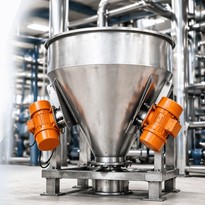
For example, a valve installed below a hopper may also require a vibrator, aeration pad or level-monitoring system to ensure that material reaches the valve consistently.
Similarly, a rotary airlock in a pneumatic conveying system must be considered alongside the blower, conveying pressure, pipeline and receiving equipment.
Choosing a Rotary Valve Around the Process
A rotary air valve should not be selected only by its nominal opening or motor size.
A reliable selection considers:
- The material being handled
- The required capacity
- Pressure differential
- Rotor design
- Valve speed
- Construction material
- Wear resistance
- Product damage risk
- Cleaning requirements
- Maintenance access
- Integration with the complete conveying or discharge system
When these factors are properly assessed, the rotary valve becomes more than a discharge device. It becomes a controlled interface between storage, feeding, conveying and dust-management equipment.
APS Technology Australia works with customers to define these requirements and select a rotary valve configuration suited to the actual operating conditions.



-205x205.jpg)



-205x205.jpg)





-205x205.jpg)